There are two ways to follow the stars with an equatorial mount as they move across the sky. You can let the telescope's drive simply "track" on them, or you can more precisely "guide" on them by making active corrections in right ascension and declination to keep a star exactly centered. With an equatorial mounting, tracking means the mount follows the stars with only its right ascension drive. No corrections are made in declination. Guiding is the process of making corrections to keep a guidestar centered by using the right ascension and declination motor controls. This can be done manually by the astrophotographer with the push buttons on the hand controller for the mount, or automatically by a computer-controlled autoguider. With an altazimuth mounting that is computer controlled, the mount moves in azimuth and altitude at the same time to track the stars. Exposure times on altazimuth mountings are limited by field rotation, unless a field de-rotator is used. The accuracy of an equatorial mounting's ability to track the stars will be determined by the mechanical quality of the mounting and the right ascension worm and gear, the accuracy of the polar alignment, and atmospheric effects such as differential atmospheric refraction. Guiding, either manually or with an autoguider, is usually necessary for astrophotos taken with long focal lengths. Depending on the accuracy of the right-ascension worm and gear and polar alignment, astrophotos made with short focal lengths may not need to be guided, they can just be tracked. Guiding means that stars are tracked more accurately, resulting in higher resolution and detail in the final image. Usually an off-axis guider or separate guidescope is used at high magnification to compensate for any irregularities in the drive, and atmospheric effects, to keep a guide star centered with much higher degree of precision than tracking alone can accomplish. For long-exposure astrophotography we also need accurate polar alignment. Guiding will not correct for poor polar alignment. A star can be guided on very accurately, but field rotation will still result if the mount is not correctly polar aligned. Deciding Whether to Guide or Just Track The first decision you will have to make is whether to take your exposures with the equatorial mount just tracking the stars, or guiding to attain higher precision. Assuming accurate polar alignment, you may be able to get away with shooting time exposures by just letting the mount track the stars and not doing any high-accuracy guiding. This will depend on the periodic error of your right ascension gear, the quality of your scope and mount, and the focal length of the imaging instrument.
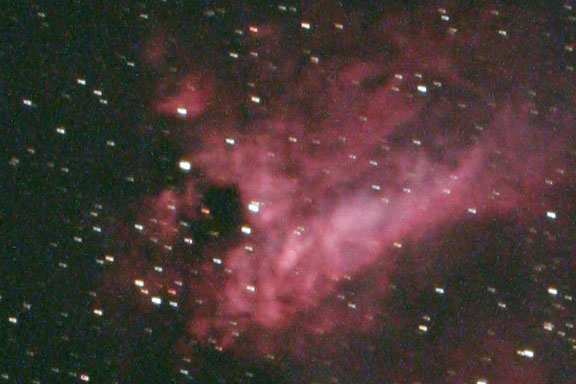
In the unguided image above, we can see the results of an exposure that was too long for the accuracy of the mount's tracking. In this case, ten 3-minute unguided exposures were made, but only one had tracking that was accurate enough to be usable. Unguided Astrophotography With the widespread use of DSLR cameras for long-exposure deep-sky astrophotography, a school of philosophy has developed that says you might be able to get by without guiding at all, depending on the focal length you are shooting at, and the drive's accuracy. This can be very attractive because guiding adds additional expense and complexity to an astrophotography outing. Manual guiding requires the expense of either an off-axis guider, or separate guidescope, rings, diagonal, guiding eyepiece and is extremely tedious. Autoguiding requires the additional expense of an autoguider and computer. Guiding is usually done for very good reasons. At long focal lengths, imperfections in the mounts drive can show up as elongated or irregular star shapes. In addition to periodic error, a star will also not track perfectly because of atmospheric factors such as refraction. But if you can keep exposures short enough, you can mitigate these effects. The philosophy of not guiding is based on the ability of your mount to track accurately enough so that your exposure can be long enough to get the data up out of the read-out noise of the camera. This is critical! Once you do this, however, you can simply stack many of these short exposures together to improve the signal-to-noise ration in the final image. To get by without guiding, your focal length must be relatively short, the optical system must be fast enough so that exposure times are relatively fast, and your camera must be low-noise enough so that these short exposures are not dominated by noise. In practice no telescope drive is accurate enough to produce perfectly tracked pictures at longer focal lengths. So a series of trial and error experimental exposures are made to see how long of an exposure you can use without it being ruined by poor tracking. Some telescope drives will track accurately for a significant portion of the worm's period, but not very well during the rest of it. In this case, the photographer simply accepts some given percentage of successful shots out of the total number of exposures. For example, you may find that you can shoot three minute exposures with a 70 percent success rate. So if you shoot 10 three-minute exposures, you just throw out the 3 bad ones and keep the 7 good ones. The best thing to do is to simply take a series of timed test exposures at the optimum exposure for your ISO and sky brightness conditions. You will need to take a sufficient number of frames at this exposure to that you go through a complete worm cycle on the mount's right ascension drive. For example, if your worm has a period of 8 minutes, and you find that 2 minute exposures are optimum, you should shoot a series of 5 two-minute exposures for a total of 10 minutes. This will go through an entire worm cycle with a little extra. You will find out how many usable frames you can get per worm cycle because frequently on drives with a lot of periodic error, you may only get usable frames at the ends of the cycle where the periodic error is reversing direction. Examine the stars in the image at high magnification. You may find that you need to increase the ISO to give shorter exposures to yield a sufficiently high number of acceptable frames. It seems a shame to waste valuable clear dark-sky time gathering photons that will improve the ultimate quality of the image and then to throw 30 percent away because of poor tracking, but this is the price some astrophotographers are willing to pay for the convenience of not having to guide. For many short focal length camera lenses (usually about 100mm or less) mounted piggyback on top of a tracking scope on an equatorial mounting, guiding is not necessary at all. This is why piggyback astrophotography is recommended first before long focal length work through a telescope. Note that even if you do not guide, accurate polar alignment is still required. If your ultimate goal is to get the best possible pictures that you can, you will find that longer exposures usually produce better results because they improve the signal-to-noise ratio. With long focal lengths, and long exposures (anything over a couple of minutes), you will almost certainly find that guiding produces the best results. Deciding Whether to Piggyback Guide or Off-Axis Guide The next decision you will have to make is whether to guide with a piggyback guide scope, or to use an off-axis guider. Piggyback guide scopes are easier to use and can be very successful if the guide scope and main scope are both refractors and the guidescope is rigidly mounted to the main imaging scope. Various degrees of success will be obtained with other combinations of main scope and guide scope. Using two scopes with mirrors usually does not work very well at all because of differential mirror movement and flexure. Off-axis guiders are more difficult to use, but if used correctly work very well with any kind of telescope. Because an off-axis guider uses the imaging scope itself to acquire a guidestar, it is inherently better by design. There can be no flexure between the guidescope and imaging scope because there is no guidescope. Using an off-axis guider with an autoguider that is not sensitive can be tedious. The off-axis guider will usually have to be rotated independently from the imaging camera to find a guide star. If a sensitive autoguider is used, such as a Lodestar, a guide star will almost always be found in the field without having to rotate the off-axis guider. A sensitive camera is a tremendous help when using an off-axis guider. The down side is that more sensitive cameras are more expensive. Guiding and Tracking Tolerances You want to keep star diameters as small as possible and not have any trailing due to poor guiding or tracking. This is determined by size of the star that can be imaged by your optical system and the resolution of the sensor in your camera. The basic questions are:
Star Sizes at the Focal Plane
What does all of this mean? In theory, in a perfect world, it means that if your scope can form a star with a FWHM of 10 microns, you need, at a minimum, a camera with a pixel that is 5 microns square to correctly sample it according to the Nyquist theorem. In the real world, you are probably only going to have one digital camera, and its pixels are going to be whatever size they are. You're not going to be able to change the pixel size to best sample the star size. Also, there aren't any dedicated astronomical CCD cameras, or DSLR cameras with 2 to 3 micron pixels. So you work with whatever you have. You could increase the focal length of the telescope to make the star size bigger to better match the Nyquist criteria to the size of your pixels, but this increases the complexity of the optical system and the difficulty of imaging and lessens the chance of success. Increasing the focal length also reduces the field of view. In a long exposure the star is almost never going to end up at its theoretical smallest size - it is going to be bigger, sometimes several times bigger.
Nevertheless, we'll go through a couple of examples for those who are interested in the details. Example 1 A 5 inch f/8 scope has an aperture of 127mm and a focal length of 1016mm and you want to shoot with a camera with 4.3 micron pixels. Here are some of the numbers for this setup:
For manual guiding, from Formula 15 we know that for a 90mm f/10 guidescope with a 12mm guiding eyepiece and 3x Barlow with a 30 arc second diameter cross-hair guide box, the most critical guiding tolerance (for a star size of 10.7 microns) would be about 1/15th of the size of the guiding eyepiece cross-hair box. A relaxed guiding tolerance (for a star that is 25 microns, would be about 1/6th of a box. If the seeing is only 5 arcseconds on a given night, then the guiding tolerance would be only 1/3 of a box. This means that the guide star would only have to be kept inside of a box that was 1/3 the size of the box formed by the cross-hairs in the guiding eyepiece. For autoguiding, we first have to calculate the image scale of the guidescope and guide camera. To simplify things, lets say we are using an off-axis guider with a guiding camera with pixels that are the same size as the imaging camera. Then all of the numbers are exactly the same for image scale. In PHD Guiding (see below for more details), each vertical space on the tracking graph will be 1 pixel, or 0.87 arcseconds. If the seeing is three arcseconds, we would have 3 / 0.87 or just about 3.5 pixels of guiding tolerance. Note that this would be for total error, so it would be plus or minus half of 3.5, or about plus or minus 1.75 pixels. If the pixels in the guiding camera are twice as big, the total allowable error would be 1/2 of that. Likewise, if the pixel size in the autoguider stayed the same as the pixel size in the imaging camera, but the focal length of the guidescope was reduced by 1/2, then the total allowable error in the tracking graph would be 1/2 of our original calculation of plus or minus 1.75 pixels, or a total allowable error of 0.875 pixels. Example 2 A 24mm camera lens working at f/2.8 has an aperture of 8.5mm.
In reality, a camera lens is never going to be able to form a star that is as small as the theoretical calculation because of the complexity of construction of the lens with multiple elements and issues such as maintaining collimation and centering of all of these lens groups and elements. Usually the stars formed by camera lenses are several times the theoretical smallest size, so the guiding tolerances can be relaxed even more. For a 24mm lens, the guiding tolerance is so loose that a properly polar-aligned mount doesn't need to be guided. Periodic Error and Tracking Tolerance Periodic error is a fundamental component of any worm and gear drive system. Since these systems cannot be perfectly manufactured there is an error component that manifests itself in the form of a sine wave. If you do not guide, and you watch a star at high power placed on the cross hair of a guiding eyepiece, you will see it drift slowly in one direction (east or west in right ascension), then return to where it started, drift slowly in the other direction, and then again return to where it started. If you plot this movement against time, it looks like a sine wave. This is the mount's periodic error. For excellent mounts, periodic error can be kept to as little as plus or minus 5 arcseconds. For reasonably good mounts, periodic error can usually be kept to plus or minus 20 to 30 arcseconds. For not-so-good mounts, the periodic error may be as much as plus or minus 60 arcseconds or more. You can measure the period error of your mount by intentionally misaligning on the pole and taking a time exposure of the length of the worm's period of revolution, and then calculating the plate scale at the focal plane in seconds of arc per millimeter for the focal length of the telescope you are using. The periodic error is then directly measured. It's easy to measure the plate scale if you shoot a wide double star of known separation. If you are shooting with a camera lens whose aperture forms a star with a spot size larger than the periodic error of the mount, the mount may not need to be guided at all for an astrophoto, it can just be tracked. For example, lets say we have a mount with a total of 30 arcseconds of periodic error and want to shoot with a 24mm f/2.8 lens. This lens produces stars that are at best 32.5 arcseconds in diameter, so we would not have to worry about correcting for the periodic error of the mount and it wouldn't need to be guided. Of course, the mount must still be accurately polar aligned, even if it is not guided. Manual Guiding Manual guiding means visually monitoring the location of a guide star and using the equatorial mount's hand controller to correct the location of the star in relation to a fixed reference such as the cross hairs in a high-power eyepiece when the star moves from its initial position. When first starting out in astrophotography, it is good to learn how to manually guide. This gives the astrophotographer a deeper understanding of what exactly is happening as the scope attempts to track a star given the vagaries of periodic and erratic error in drive systems, movement due to seeing, drift due to inaccurate polar alignment, and other things that can go wrong. Manual guiding during long exposures gives an appreciation of what can go wrong, and also builds physical prowess and moral fortitude, particularly on cold nights. To guide manually you will need a high-magnification guiding eyepiece with an illuminated cross-hair reticle. The reticle comes in different designs such as single cross hairs, double cross hairs, and other more complicated markings. The best design for manual guiding is the double cross hair model. We can use Formula 14 to calculate the amount of magnification needed for accurate manual guiding. In the case of an off-axis guider, the magnification of the imaging scope and guiding scope are the same. Often a Barlow is used in the off-axis guider with a 12mm guiding eyepiece to increase the magnification and accuracy of visual guiding. Use of a Barlow is usually not necessary if an autoguider is used because of its more accurate guiding ability compared to the human eye. In the case of a separate guidescope, a rule of thumb for visual guiding is that magnification of the guidescope should be about the focal length of the imaging scope in millimeters divided by 5. So if your main imaging scope is 1,000mm of focal length, your guiding magnification in a separate guidescope should be about 200x (1,000/5). Once we have calculated the magnification needed, we need to figure out how to relate what we are seeing in the guiding eyepiece (a star in reference to the double cross hairs) to the final star size in the image. When a scope is manually guided, a cross-hair eyepiece is used to keep the guidestar centered. These eyepieces are in the range of 5 to 12mm in focal length and usually have a double cross hair that forms a box in the center of the field. This box is about 0.2mm on a side. Most are this size, but this should be checked with the manufacturer of the guiding eyepiece. If the guiding tolerance is not critical, for example with a wide-angle lens, the guide star may just need to be kept in the box. If the tolerance is very critical, the guidestar may have to be positioned behind the intersection of two of the lines, and not allowed to drift more than one star diameter off of this mark. Autoguiding Experience with manual guiding will make an astrophotographer really appreciate an autoguider. An autoguider is usually a CCD camera or webcam that is connected to a computer that analyses motions of a guidestar and automatically issues corrections to the drive system of the mount. Autoguiders are capable of much higher guiding accuracy than manual guiding. Some autoguiders can have dedicated computers built into them, such as in the SBIG ST-4, ST-V and SG-4. Some regular CCD cameras, such as the SBIG ST-402ME, can be used as autoguiders with special software that runs on a separate computer. Orion's inexpensive StarShoot Autoguider is made especially for autoguiding. Even simple inexpensive webcams can be used as autoguiders with a computer with programs such as PHD Guiding or Guidedog, and MetaGuide. To calculate the necessary guiding accuracy for an autoguider, you first calculate the spot size of the star at the focal plane using Formula 5 and any allowable drift factor, and compare it to the size of the pixels in the autoguider and the accuracy of the algorithm that sub-samples the pixels. For cameras that use modern autoguiding software like PHD, star locations can be calculated to sub-pixel accuracy, so shorter focal length guidescopes can be used than in the past for manual guiding. If the seeing is not allowing the theoretical resolution of the telescope to be reached, then the corresponding guiding tolerance can be relaxed. Piggyback Guidescope vs Off-Axis Guider In this arrangement, you will have a second smaller refractor riding piggyback on top of the imaging scope. Usually the main scope is also a refractor. During the days of film astrophotography, many people tried to piggyback guide all types of imaging scopes with many different types of guidescopes. People tried refractor guidescopes on top of Newtonians, SCTs, whatever. People tried guiding with small SCTs, Maksutovs, you name it. When I first started out, I even foolishly tried guiding a 12 inch f/8 Newtonian with a Celestron 8 inch SCT that was mounted piggyback on the main scope with wooden rings and the C8 held in a web of string - just in case it fell out. Well, guess what I found out? It didn't work. Most other people found out the same thing with a lot of other combinations. The problem in those days was the long exposures required for film almost always proved fatal because of flexure, or the mirror in one or both scopes moving, or the mirror moved when the refractor didn't. Like Murphy's law, it pretty much came down to this: if something can move during an exposure, it will. The only consistently successful way to piggy-back guide, in most cases, was to use a refractor as a guidescope, in solid well-mounted rings, on top of another larger refractor as the main imaging scope. There there even be flexure in this kind of setup, but I would say that I have been 95+ percent successful doing long-exposure deep-sky astrophotography with this setup. Other people claimed to have achieved success with other setups and types of scopes by locking down the mirrors, or building their scopes like a tank to prevent flexure, but these success stories were few and far between. The hard-learned, generally accepted wisdom is that you should use an off-axis guider to guide any kind of large scope with a mirror in it. This situation may have changed slightly with the advent of astrophotography with DSLR cameras because shorter exposures are used and these are combined to equal one longer exposure. Less things can go wrong in a short 5-minute exposure than in a long 60-minute exposure. If you are willing to accept a lesser percentage success rate, and your exposures are limited to 5 minutes or less, you may be able to piggyback guide an SCT with a small refractor. You are probably asking for trouble if you try to guide with a mirror guidescope on top of a mirror main-imaging scope. Using a Separate Guiding Scope After you have acquired the deep-sky object to be photographed, and framed it and focused the camera, it is time to acquire a guidestar. If you have researched guide stars during a planning session before going out, you will know exactly where to look for one. If not, you'll have to hunt around to find one that is bright enough to guide on. For manual guiding, the brighter the guidestar the better. For autoguiding with the ST-4, you can usually guide on any star you can see visually in the guiding eyepiece. Put a wide-angle eyepiece in the guidescope to help first acquire the guidestar. Loosen the three screws that hold the guidescope in the ring nearest to the camera and move just the tube of the guidescope (not the whole mount!) to find a guide star. If you find a suitably bright star but can't quite get it to the center of the field, lock down these three screws, and then loose the three on the guidescope ring closest to the sky end of the guidescope. This will give you additional aiming movement and allow you to center the star if you run out of movement on the bottom guidescope ring. After you have coarsely centered the guide star in the wide angle eyepiece, switch over to the high-power cross-hair guiding eyepiece. Use the three alignment screws in the guidescope rings to continue tweaking the centering of the guide star until it is inside the box formed by the double cross hairs. Then lock down the guidescope tight in both rings. Double check to be sure the guidestar is still centered, and then check to be sure that the deep-sky object is still framed correctly in the main imaging scope. Now orient the cross hairs in the guiding eyepiece so that they correspond with east-west and north-south. This is easily done by simply running the mount in Right Ascension or Declination with the hand controller. If manually guiding, correct orientation of the hand controller is critical because you will need to push only one button to make a correction when the guide star moves. Practice pushing the buttons on the hand controller to memorize which one moves the star in a particular direction. Adjust the brightness of the reticle so that the guide star can be easily seen. The lower the brightness of the reticle the better. Accurately focus the guide star in the guiding scope and lock down the focus. If you are imaging with a long focal length scope and guiding tolerances are critical, place the guide star behind the intersection of one of the cross hairs. Memorize which intersection you are using in case you look away for a moment or two and the guide star moves off the intersection. Now practice guiding for a while before you start the exposure in the camera. If you are going to use the mounts periodic error correction (PEC), train it during this period. If you are using an autoguider, all of the steps are basically the same up to this point. Find a guide star and center it in the guiding eyepiece. This will ensure that it is on the small chip in the autoguider. Replace the guiding eyepiece with the autoguider. Orient the autoguider so that the chip lines up with right ascension and declination. Most autoguider chips are aligned with the label on the back of the guiding head, so it is easy to orient by making the label parallel to either right ascension or declination, it doesn't matter which. It is usually not even critical to have the chip aligned perfectly, because software can compensate, but it makes the readouts make more sense when you are trying to interpret them. Then go through the autoguider setup and calibration procedure and make sure the autoguider if functioning correctly. An autoguider must be calibrated. In this step, the autoguider issues a command to move the mount for a given period of time, and then the amount that the guidestar moves is noted. This is repeated and averaged several times for more accuracy. Then the autoguider software knows how long of a move command to issue to correct for a given amount of tracking error during the imaging run. Focus is critical when faint stars are used in an autoguider and focusing by trial and error can be tedious. If you are using an autoguider with a separate guidescope, you can save yourself a lot of work by par-focalizing the guiding eyepiece to the focus of the autoguider. This is done by first focusing the autoguider by trial an error by visual inspection of the star in software, or using a numerical readout of the star's brightness. The highest brightness values for a guidestar usually correspond to the best focus. However, brightness values can vary with seeing, so it is advised that several exposures of the guidestar be averaged to determine a brightness value. Then the guidescope's focus is adjusted and the brightness values averaged again. This procedure is repeated until the point of best focus is passed and the brightness values begin to decrease again. Then focus is moved back in the other direction to come back to the point of best focus. Only by going through and past the point of best focus can you really determine that the point of best focus has truly been achieved. If you use a bright enough guidestar and a short enough exposure with a guide camera that has a fast download time, you can almost focus the guiding camera by eye in real time. Once focus is obtained, the focuser of the guidescope is locked down. Then the autoguider is removed and replaced with the guiding eyepiece with a par-focalization ring. The guiding eyepiece is focused by sliding it in and out of the draw tube, and when it is in focus, the par-focalization ring is locked down flush with the edge of the draw tube. This way, the next time out, you simply focus the guidescope with the par-focalized guiding eyepiece, lock down the guidescope focuser, and then substitute the autoguider. No additional focusing is necessary. Use of a par-focalized guiding eyepiece then greatly simplifies use of the autoguider. Since the CCD chips in autoguiders and web cams can be very small, placing the guide star on the chip is made easier by centering it first in the box made by the cross hairs of the guiding eyepiece. Then the scope is focused to the par-focalized guiding eyepiece, and the autoguider is substituted for the guiding eyepiece. The autoguider will then be centered on the guidestar as well as focused. Using an Off-Axis Guider An off-axis guider uses a small prism or mirror to pick off a very small portion of the light cone from the main imaging scope, usually in an area that is just outside of the field of view at the sensor of the camera. The beauty of an off-axis guider is that since the image of the guide star is formed by the main imaging scope, any movement in the image, whether from mirror movement, tracking error, or flexure, will be identical in both the guide star and the image formed on the sensor of the DSLR camera. It is a perfect guider by design that compensates for any irregularities. The problem with an off-axis guider is that they can be difficult to use in practice with a web cam or other CCD camera that requires a bright star to guide on. The guide star must be located in a narrow ring around the object being photographed. For manual guiding, the eyepiece can end up at difficult-to-use angles. For autoguiders, if the main scope is a fast Newtonian, or other type of scope that has poor off-axis images, the defective star image may be difficult to guide on. Many telescopes produce stars that are less than perfect in the corners and edges of the frame. Coma is a particular problem in fast Newtonians, and astigmatism is frequently present in scopes that have a curved focal plane, as most scopes do. Because an off-axis guider picks off a star on the edge of the field, these stellar aberrations can cause significant problems. Many are so bad that an autoguider cannot even guide on them. In these cases placing the off-axis guider behind a field flattener or coma corrector can help significantly, although not all scopes will have enough back focus to accomplish this. Most of the steps in acquiring a guide star are the same as listed above for a separate guide scope, but there are a couple of important differences. If you are using an off-axis guider, you will probably need to rotate it radially to locate a guidestar. You may also need to adjust the lateral position of the guiding eyepiece. The orientation be can be figured out in advance by plotting the location of the pick-off prism or mirror in relation to the size of the imaging sensor on an overlay that is used with a star chart, or planetarium program. The most important consideration in using an off-axis guider is that the focus of the guiding eyepiece or autoguider must be achieved separately from the main imaging scope. The process should be accomplished in this order:
Focusing the guiding eyepiece for manual guiding is simply accomplished by visual inspection of the star image. Focusing the autoguider must be accomplished by examining the star image or brightness readout in the software. If you use an autoguider, it can save you a lot of work if you use a par-focalizing ring to fix the location of focus on the tube of the autoguider or webcam. This is accomplished by putting a par-focalizing ring on the tube, but leaving it loose at first. The autoguider or webcam is then focused through software. Once focus is obtained, the autoguider or webcam is locked down in the off-axis guider's eyepiece holder. Only then is the par-focalizing ring made flush with the base of the off-axis guider's eyepiece holder tube, and the ring is locked down. The next time the autoguider or webcam is used, it is simply inserted into the off-axis guider's eyepiece holder and it should be in focus. It makes sense to check this focus occasionally just to be sure nothing has moved. Using a highly sensitive guiding camera like an SBIG ST-i or SG-4, or Starlight Express Lodestar, can make your life much easier with an off-axis guider. There will usually be a star in the field that is bright enough to guide on with one of these sensitive cameras, and you won't have to physically move the OAG to hunt for a guidestar. Practical Guiding Considerations
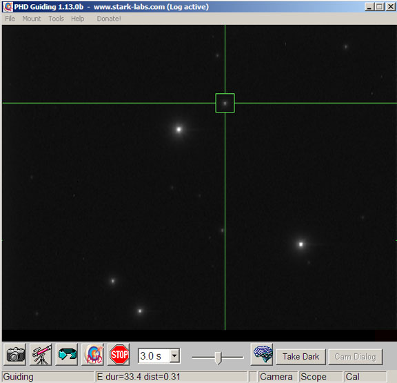
PHD Guiding PHD Guiding is a very useful piece of free software by Craig Stark used to control your mount with an autoguider. It runs on both Mac and Windows computers.
"PHD", which stands for "Push Here Dummy," is very simple to use. Just start by clicking on the camera icon at lower left and work your way to the right clicking on each icon after you are finished with the task of the previous icon. The icons are for:
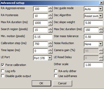
The next item is a pull-down menus for guide camera exposures. You can increase this if you can't find a star, or decrease it if the star is too bright or too dim. It is better to guide on a star that is not too bright or saturated. It is also better to guide on a star that is not too dim as it will have a low signal-to-noise ratio. Next is a slider that adjusts the screen brightness in PHD. The next icon is the Brain. This calls up the Advanced Panel, which allows the fine tuning of different settings in PHD. Most times the default settings will work fine, but for large scopes with long focal lengths some settings may need to be adjusted.
For longer focal length scopes, you may need to decrease the Max RA and Max Dec and Calibration step durations, and increase the size of Min Motion in pixels. Min Motion is the minimum amount of movement of the guidestar allowed before a correction is issued. It is also probably a good idea to decrease the RA Aggressiveness a bit for any focal length scope. The button marked "Take Dark" will take a dark frame and subtract it from each subsequent guiding image. Your scope has to be capped so that it is light-tight to take a dark frame. Dark frames can be helpful under high ambient temperatures and with long guide exposures. Darks will remove any hot pixels which can be mistaken for a star. Some cameras have more hot pixels than others. You don't absolutely need to take a dark frame if you don't have a lot of hot pixels and your guide star is not too close to one. The Guiding Graph Under the Tools menu at the top of the screen, you can also call enable the guiding graph, which will give you a graphical representation of how your guiding is doing, and allow you to tweak some guiding parameters on the fly while guiding is active. Each vertical line space represents movement of the guidestar by one pixel. Each horizontal tick represents one exposure of the guidestar. Two numerical readouts are also given, one for the "Osc Index" and one for "RMS". Guiding parameters that can be adjusted run along the bottom of the guiding graph.
Note that the oscillation index and RMS readouts are only for the right ascension guiding. Ideally, there will be no oscillation in the declination because you will have determined the direction of drift in dec and enabled corrections in only that direction.
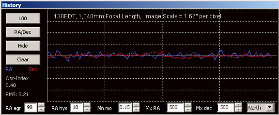
In the PHD graph 1 seen above, the guiding was excellent. The RMS was 0.21 pixels times the image scale of 1.66 arcseconds per pixel, which equals an RMS value of 0.3486 arcseconds. Looking at the graph, we can also see that no individual peak or valley in the graph lines for either the right ascension or declination went more than about plus or minus one pixel, which is a total error of about 1.66 arcseconds. Given that the seeing this night was around 2-3 arcseconds, this guiding held stars sizes to a minimum and produced nice tight round stars in the image.
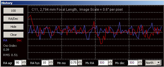
In the PHD graph 2, we see that the RMS was 0.51 pixels. This is more than twice as much as in graph 1. We can also see that the largest excursion in the dec was plus 2.5 pixels and minus 1.5 pixels for a total of 4 pixels. We might conclude that the guiding was bad in this image if we only looked at the graph and did not consider the image scale per pixel. However, we need to realize that this guiding was done through an off-axis guider in a C11 telescope. The image scale here is just 0.6 arcseconds per pixel. So we have an RMS score of 0.51 x 0.6" = 0.306", which is actually better in terms of arcseconds than graph 1. Peak to peak of 4 pixels is 4 x 0.6" = 2.4 arcseconds. This is not as good as graph 1, but it is still within the tolerances for seeing of 2-3 arcseconds is a long exposure. We probably don't want the peaks and valleys of the graph to be much larger than this to get acceptable guiding with the C11.
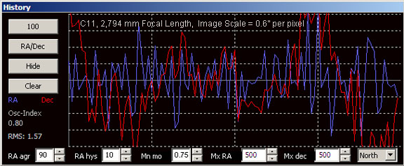
In PHD graph 3, the RMS value was 1.57 pixels. This graph is also from the C11 with an image scale of 0.6 arcseconds per pixel, so this indicates an average error of 1.57 x 0.6" = 0.942", or about 3 times worse than graph 2. Looking at the graph, we can also see large excursions in both right ascension and declination - so large that they actually go off the top and bottom of the graph. This means a total plus or minus error of 8 pixels, or 8 x 0.6" = 4.8 arcseconds. The guiding in this image is not very good, and upon examination, the stars were both bloated and trailed. The poor guiding this night was attributable to the extremely poor seeing. The lessons to take away from studying these three graphs is that the appearance of the graph will be influenced not only by the quality of the guiding, but also by the quality of the seeing and focal length and image scale of your guiding system. In addition to the RMS readout, you also need to consider individual plus and minus excursions which can lead to trailing but which may not be reflected in the RMS value. Note also that the RMS readout is for right ascension only. Your right ascension could be tracking perfectly, but if your dec is oscillating wildly, you will have great RMS numbers, but trailed stars in declination. The bottom line is that, as they say, "the proof is in the pudding." The RMS readout and graph in particular can be good indicators of how the guiding is going, but the bottom line is the size and shape of the stars in the final image. Once you have your mount and guiding setup working well, the biggest factor that will affect the accuracy of your guiding is the seeing. This is especially true as you increase the focal length. When I shoot at 2,800mm of focal length with my C11, on nights of poor seeing, the guiding is usually poor, no matter what settings I use for the different parameters in PHD. PHD Tips and Tricks
Evaluation Evaluate your guiding. Keep an eye on the graph. Remember the scale is in pixels. Large erratic excursions up or down indicate a problem. Keep an eye on the oscillation index and RMS. Remember though that these are general indicators only. The ultimate test of your guiding accuracy for your particular system is to examine the stars in the image at high magnification. If they are bloated, you may have bad seeing. If they are elongated, you have a guiding / tracking problem, or possibly flexure between the main imaging scope and guidescope. If stars are trailed east-west, there is a problem in right ascension. If stars are trailed north-south, there is a problem in declination. If stars are trailed on a diagonal between right ascension and declination, you may have problems in both axes, or you may have flexure, or you may be using incorrect settings in PHD. In general, try making changes to lower values in the adjustments to start out with. Oscillations are usually caused by the mount trying to chase the seeing with too small of a minimum motion value and values too large for RA aggressiveness. Try a longer exposure time for bad seeing, and increase the size of the minimum motion for longer focal lengths. At long focal lengths, the seeing in especially important. On nights of bad seeing, when attempting to shoot with my C11, I have found that the guiding will be poor, no matter what settings are used. How Long Can You Shoot with an Altazimuth Mounting? If you are using an altazimuth mounting that is not polar aligned with the north celestial pole, you can still shoot time exposures, but they will be limited in length by field rotation. Because field rotation in an angular error, it is independent of focal length. In a study by Michael Covington, he found that for an observer located at 40 degrees north latitude, photographing an object on the celestial equator and meridian, the field will rotate at 0.2 degrees per minute, limiting the maximum exposure to 30 seconds. With exposures this short, a fast optical system is recommended. It is possible to shoot 30 second exposures at ISO 1600 with a very fast aperture and add or average a lot of short exposures to equal a longer one and get good results. See the astrophotos of John Ambrose for examples. For longer exposures an equatorial mount is required, or a field de-rotator. Field de-rotators however will only work at prime focus of the telescopes they are designed for and will not help with piggyback photography.
|
|||||||||||||||||
|
Back | Up | Next |